

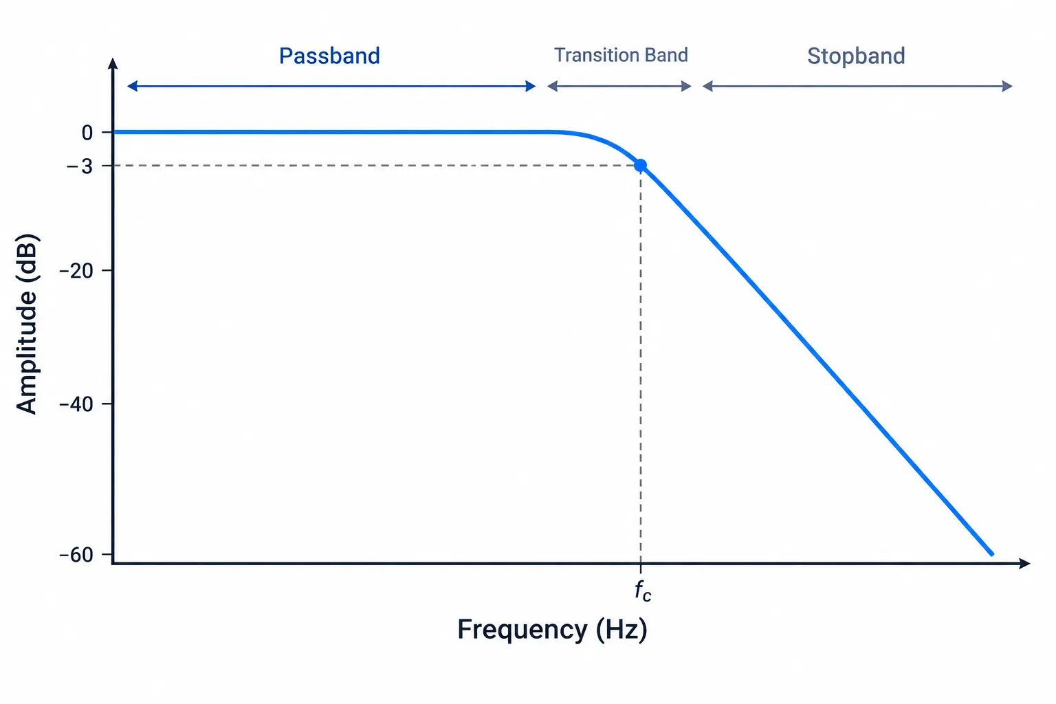
A low-pass filter lets frequencies below a chosen cutoff through and turns down the ones above it. A high-pass filter does the opposite. At the “cutoff” itself, a low-pass still passes about 70.7% of the signal’s amplitude. This guide gives you the numbers for mixing, circuits, code and subwoofers. If you came for the pilot’s meaning of “low pass”, skip to the section titled “Low pass in aviation”.
Key takeaways
- A low-pass passes the lows and cuts the highs. A high-pass passes the highs and cuts the lows.
- The cutoff is the -3 dB (half-power) point. The filter keeps cutting gradually above it, so it is not a wall.
- Each filter order adds 6 dB per octave: 6, 12, 18, 24 and up to 48 dB/oct.
- A second-order Butterworth filter uses Q = 0.707. That gives the flattest passband with no peak.
- For a subwoofer, start at 80 Hz (THX) and set it at least 10 Hz above the lowest frequency your main speakers play cleanly.
Find your section by what you need:
| You want | Section to read |
|---|---|
| The definition and the -3 dB cutoff | What does low pass mean? |
| Low-pass vs high-pass, circuits and curves | Low pass vs high pass: how to tell them apart |
| Slopes, Butterworth Q and resonance | Slope, order and resonance explained |
| RC calculator and part values | Low-pass filter circuit and calculator |
| Equations and C code | Digital low-pass filters: equation and C code |
| Mixing settings | How to use a low-pass filter in a mix |
| Free plugins and Audacity settings | Best free low-pass filters in open-source software |
| Hiss and hum | Does a low-pass filter reduce noise? |
| Subwoofer settings | Subwoofer low-pass settings |
| Aviation meaning | Low pass in aviation |
Fact-checked
We checked these key facts against the sources named, on November 15, 2026:
- R = 1/(2π × 20,000 × 0.000000001) ≈ 7,958 Ω (source: flux.ai)
- Time constant: 1,000 × 0.0000001 = 0.0001 s, or 100 µs (source: flux.ai)
- In the US it sits at 60 Hz plus harmonics at 120 Hz, 180 Hz and up (source: nema.org)
- Cutoff: fc = 1/(2π × 0.0001) = 1/0.000628 ≈ 1,592 Hz, about 1.59 kHz (source: flux.ai)
- For a subwoofer-style 100 Hz cutoff with R = 10 kΩ, you need C ≈ 159 nF (source: electronics-tutorials.ws)
What does low pass mean?
A low-pass filter keeps the frequencies below its cutoff and gets steadily quieter above it. On a frequency-response graph you see a flat line across the lows, a gentle bend at the cutoff, then a slope down to the right. An analog synth filter, a subwoofer crossover and a few lines of C all reduce to that one shape.
You will also hear it called an LPF or a high-cut filter. “Low filter” turns up too, but it isn’t a standard term. All these names mean the same filter. The cut changes frequency content, not volume or pitch. Pull a low-pass down on a drum loop and the cymbals and the crack of the snare fade first, while the kick stays at the same level. Audio engineers, electronics designers and DSP programmers all use the word this way. Pilots use it for something else entirely: a flight manoeuvre over a runway, which has its own section at the end.
Passband, cutoff and stopband
A low-pass response has three regions plus a transition between them:
- The passband runs from 0 Hz up to the cutoff. Signals in it come through at close to full level.
- The cutoff frequency (also called the corner frequency) is where the curve bends, measured at -3 dB.
- The stopband lies above that. The level keeps falling there, and the slope sets how fast.
- The transition band sits between the cutoff and the deep stopband. Gentle filters have a wide one, steep filters a narrow one.
Here is a worked example. A low-pass at 1 kHz with a 12 dB/octave slope leaves 200 Hz almost untouched. It turns 1 kHz down by 3 dB, 2 kHz by about 12 dB and 4 kHz by about 24 dB. A sound at 8 kHz is still there, only quieter. The current Audacity manual makes the same point: the cutoff marks where attenuation begins, not where sound stops. Its definition also covers a detail many explainers skip. Because the cutoff sits at -3 dB, frequencies just below it are already slightly attenuated, and that attenuation shrinks as you move further down.
Why the cutoff is the -3 dB point, not a wall
At the cutoff, the output amplitude is 0.707 of the input. That ratio is -3 dB, which is half the power. EE Power’s technical article on RC low-pass cutoff frequency and transfer functions adds that a first-order filter’s phase has shifted by -45° at that point. Engineers chose -3 dB because half power is easy to define. It isn’t the point where you start to hear a change.
On a full mix, a 3 dB dip in the top octave is easy to notice. On a bass guitar with little energy above 5 kHz, a low-pass at 5 kHz can sound like nothing happened. That’s why a cutoff copied from someone else’s session rarely works. What you hear depends on how much of the sound sits near and above the cutoff.
Did you know?
At its rated cutoff frequency, a low-pass filter is still passing about 70.7% of the signal’s amplitude (-3 dB, or half power), according to EE Power’s RC low-pass reference. The “cutoff” is really where the cutting starts.
Low pass vs high pass: how to tell them apart
A high-pass filter is the mirror image of a low-pass. It lets frequencies above its cutoff through and turns down the ones below, so it removes rumble, hum and boom. A low-pass removes hiss, harshness and air. Both follow the same rules: the cutoff is at -3 dB and each order adds 6 dB of slope. Only the direction is different.
Mixing engineers often call a high-pass a “low cut” and a low-pass a “high cut”. People mix these up because the word in each name points at the opposite end of the spectrum. One rule always works: the name says what passes. Low pass, lows pass. High pass, highs pass.
Two related shapes complete the set. A band-pass filter is a high-pass and a low-pass in series, so only a band in the middle survives. The classic telephone sound is a band-pass from roughly 300 Hz to 3.4 kHz. A shelf raises or lowers everything above or below a frequency by a fixed amount and then levels off. It doesn’t keep falling.
| Filter | Passes | Cuts | Typical audio job |
|---|---|---|---|
| Low-pass (high cut) | Below cutoff | Above cutoff | Darken reverb, tame fizz, subwoofer feed |
| High-pass (low cut) | Above cutoff | Below cutoff | Remove rumble, clear mud from vocals |
| Band-pass | A band between two cutoffs | Both ends | Telephone and radio effects |
| High shelf | Everything, highs at a set offset | Highs by a fixed dB | Gentle brightness control |
| Low shelf | Everything, lows at a set offset | Lows by a fixed dB | Gentle bass control |
Reading the circuit diagram
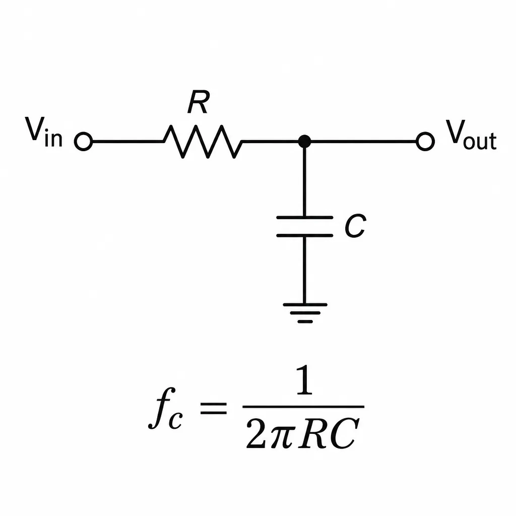
In a passive RC circuit, look at where the capacitor sits. A low-pass has a series resistor followed by a capacitor to ground, and the output is taken across the capacitor. A capacitor’s impedance falls as frequency rises. At high frequencies it shorts the signal to ground, and at low frequencies it barely loads the line. A high-pass swaps the parts: a series capacitor, then a resistor to ground, with the output across the resistor. Low frequencies can’t get past the series capacitor.
Inductors flip the rule, because an inductor’s impedance rises with frequency. An inductor in series with the signal makes a low-pass. That’s why a passive loudspeaker crossover puts a coil in series with the woofer and a capacitor in series with the tweeter.
| Circuit | Low-pass layout | High-pass layout |
|---|---|---|
| RC | Series R, capacitor to ground | Series C, resistor to ground |
| RL | Series inductor, resistor to ground | Series R, inductor to ground |
| Speaker crossover | Coil in series with woofer | Capacitor in series with tweeter |
Reading the response curve
On a frequency-response graph, frequency runs left to right (low to high) and level runs up and down. A low-pass curve is flat on the left and drops on the right. A high-pass curve rises from the left and is flat on the right. A band-pass looks like a hill. Plugin EQ displays draw exactly these shapes, so you can identify any filter at a glance.
Two more details are worth checking. A bump just before the drop means the filter has resonance (covered below). A curve that falls and then flattens at a lower level, instead of dropping forever, is a shelf, not a pass filter.
Low-pass vs high shelf: remove or just tame highs
Use a low-pass when the content above a frequency is unwanted: hiss, aliasing fizz, cymbal bleed on a bass mic, or the top end of a reverb tail. Use a high shelf when you want to keep that content, only quieter. A -3 dB shelf above 8 kHz on a harsh vocal leaves the breath and air audible. A low-pass at 8 kHz removes more of them the higher they sit.
Low-passing everything has a real cost. A low-passed lead vocal tends to sound like it is behind a curtain. A shelf usually does the job better, and so does a de-esser if the problem is sibilance.
Producer tip
If you only want less brightness and still want to keep the air, reach for a high shelf at -2 to -4 dB instead of a low-pass. Save the low-pass for content you actually want gone.
Slope, order and resonance explained
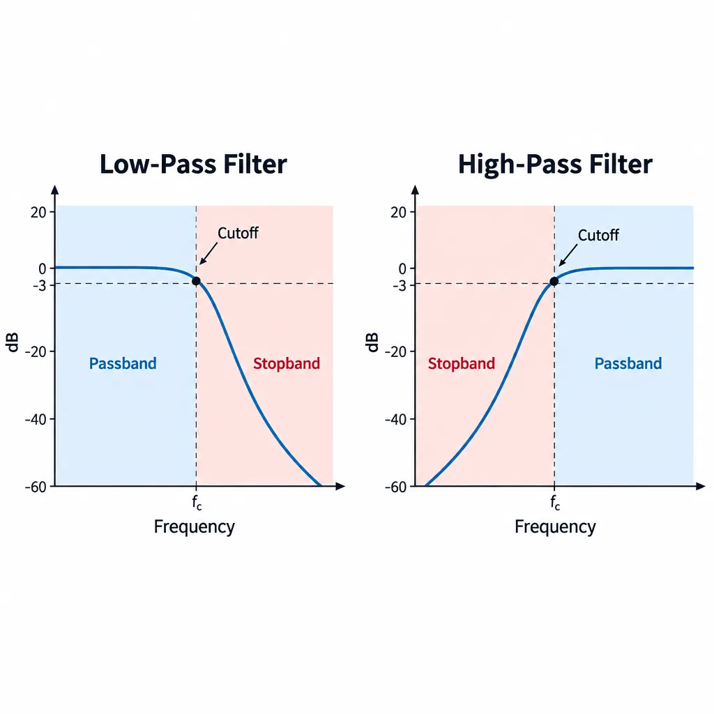
The slope tells you how fast a filter cuts once you are past the cutoff. Each order (also called a pole) adds 6 dB per octave, so an nth-order filter ends up rolling off at 6n dB per octave. A first-order filter falls at 6 dB/oct, second order at 12, fourth order at 24 and eighth order at 48.
An octave is a doubling of frequency. So “24 dB/oct at 1 kHz” means roughly 24 dB down at 2 kHz and 48 dB down at 4 kHz, once the curve has settled into its slope. Close to the cutoff the curve is still bending, so the real figures differ slightly from the ideal ones. The table below gives exact values for Butterworth filters, using attenuation = 10·log10(1 + (f/fc)^(2n)).
| Order / poles | Slope (dB/oct) | Slope (dB/decade) | Level 1 octave above cutoff | Level 2 octaves above cutoff | Typical use |
|---|---|---|---|---|---|
| 1 | 6 | 20 | -7.0 dB | -12.3 dB | Gentle tone shaping, RC hiss filters |
| 2 | 12 | 40 | -12.3 dB | -24.1 dB | Most mix cleanup, synth filters, biquads |
| 3 | 18 | 60 | -18.1 dB | -36.0 dB | Speaker crossovers, firmer cleanup |
| 4 | 24 | 80 | -24.1 dB | -48.2 dB | Classic synth ladder sound, subwoofer LPF |
| 6 | 36 | 120 | -36.1 dB | -72.2 dB | Hard effects, steep band limiting |
| 8 | 48 | 160 | -48.2 dB | -96.3 dB | Telephone and underwater effects |
Every one of these is still -3.01 dB at the cutoff. Order changes how quickly the filter dives after the cutoff. It doesn’t move the -3 dB point.
dB per octave vs dB per decade
Audio people count in octaves (doubling the frequency). Electronics textbooks often count in decades (ten times the frequency). The conversion is fixed: 6 dB/octave equals 20 dB/decade, so a second-order filter is 12 dB/oct or 40 dB/decade. If an application note says a filter rolls off at 80 dB/decade, it is a fourth-order, 24 dB/oct design. The two units describe the same slope.
Butterworth and Q = 0.707
A Butterworth filter has the flattest possible passband: no ripple and no bump before the cutoff, just a smooth bend. A second-order Butterworth low-pass has Q = 0.7071 (1/√2), sits at exactly -3.01 dB at the cutoff and rolls off at 12 dB/oct.
Higher orders are built as a chain of second-order sections, each with its own Q, given by Qk = 1/(2 sin((2k−1)π/(2n))). A fourth-order Butterworth splits into two sections with Q values of about 0.541 and 1.307. Neither one is 0.707, yet together they produce the flat 24 dB/oct response. A plugin with a “24 dB” Butterworth mode does this internally.
Other filter families trade things differently:
| Family | Passband | Roll-off near cutoff | Typical use |
|---|---|---|---|
| Butterworth | Maximally flat | Moderate | General audio cleanup, EQ plugins |
| Chebyshev | Ripple | Faster | Steep band limiting where ripple is acceptable |
| Linkwitz-Riley | Flat when outputs are summed | Two Butterworths in series | Loudspeaker and subwoofer crossovers |
Resonance: sweep tool, not a mix fixer
Q is the engineering measure of how sharply a filter peaks at its cutoff. “Resonance” is the synth-panel name for the control that raises Q, usually through feedback. On most plugins the resonance knob is in effect a Q control. In a second-order low-pass, the gain at the cutoff equals Q, so any Q above 0.707 creates a bump:
| Q | Level at cutoff | Peak above passband | Character |
|---|---|---|---|
| 0.5 | -6.0 dB | none | Soft, droopy knee |
| 0.707 | -3.0 dB | none (Butterworth) | Flat, neutral cleanup |
| 1.0 | 0 dB | about +1.2 dB | Slight emphasis |
| 2.0 | +6.0 dB | about +6.3 dB | Audible “wah” quality |
| 5.0 | +14.0 dB | about +14.0 dB | Squelchy, near self-oscillation |
In sound design, that peak is the point. Sweep a resonant low-pass across a sawtooth and you get the classic acid or filter-sweep sound. In a mix it is often a trap. A low-pass at 300 Hz with Q = 2 on a bass adds about 6 dB right in the low-mid mud zone, which is the opposite of what cleanup needs. When mixing, keep resonance at its minimum or at 0.707. Raise it only when you want the filter itself to be heard.
Low-pass filter circuit and calculator
A first-order RC low-pass has a cutoff of fc = 1/(2πRC), with R in ohms, C in farads and fc in hertz. In angular terms, ωc = 1/RC. The product RC is the time constant τ (tau), in seconds.
This is the most common filter in electronics. It shows up in guitar tone controls, DAC output stages, sensor smoothing and the hiss filters at the inputs of many audio circuits. A single RC stage gives 6 dB/oct. For steeper slopes you either cascade stages through buffers or move to an active second-order design.
Worked example: 1 kΩ + 100 nF
Take R = 1 kΩ (1,000 Ω) and C = 100 nF (0.0000001 F):
- Time constant: 1,000 × 0.0000001 = 0.0001 s, or 100 µs.
- Cutoff: fc = 1/(2π × 0.0001) = 1/0.000628 ≈ 1,592 Hz, about 1.59 kHz.
- At 1.59 kHz the output is 0.707 of the input, with a -45° phase shift.
- At 3.18 kHz it is about 7 dB down, and at 15.9 kHz (one decade up) about 20 dB down.
Only the product RC matters, so 10 kΩ with 10 nF gives exactly the same cutoff. Use the table below as a quick calculator for common part pairs.
| R | C | Time constant (RC) | Cutoff fc |
|---|---|---|---|
| 1 kΩ | 1 µF | 1 ms | 159 Hz |
| 10 kΩ | 100 nF | 1 ms | 159 Hz |
| 1 kΩ | 100 nF | 100 µs | 1.59 kHz |
| 10 kΩ | 10 nF | 100 µs | 1.59 kHz |
| 4.7 kΩ | 10 nF | 47 µs | 3.39 kHz |
| 22 kΩ | 1 nF | 22 µs | 7.23 kHz |
| 10 kΩ | 1 nF | 10 µs | 15.9 kHz |
| 7.5 kΩ | 1 nF | 7.5 µs | 21.2 kHz |
Choosing parts for a target cutoff
Rearrange the formula to find the part you’re missing: R = 1/(2π·fc·C) or C = 1/(2π·fc·R). Usually you fix the capacitor first, because capacitors come in fewer convenient values, and then choose a resistor.
For example, say you want an anti-hiss filter around 20 kHz using a 1 nF capacitor. R = 1/(2π × 20,000 × 0.000000001) ≈ 7,958 Ω. The nearest standard values are 7.5 kΩ (21.2 kHz) and 8.2 kΩ (19.4 kHz). For a subwoofer-style 100 Hz cutoff with R = 10 kΩ, you need C ≈ 159 nF. A stock 150 nF part lands at about 106 Hz.
Two real-world effects move the cutoff. The output impedance of the source driving the filter adds to R, and the load after the filter sits in parallel with C. Keep the load at least ten times higher than R, or buffer the output with an op-amp.
Going second order: Sallen-Key
The standard active circuit for 12 dB/oct with an adjustable Q is the Sallen-Key topology: two resistors, two capacitors and one op-amp. Texas Instruments’ application note SLOA049, Active Low-Pass Filter Design, works through a second-order Sallen-Key low-pass at 1 kHz with Q = 0.707, which gives a Butterworth response.
In the unity-gain version with equal resistors, Q = 0.5 × √(C1/C2), where C1 is the feedback capacitor and C2 goes to ground. Make C1 twice C2 and you get Q = 0.707. With R = 10 kΩ and a 1 kHz target, that comes to about 22 nF for C1 and 11 nF for C2. Cascade two Sallen-Key stages using the Butterworth section Qs (0.541 and 1.307) and you get a flat 24 dB/oct filter.
Watch out
Bench-testing filters on mains-powered gear or speaker-level outputs carries real shock and hearing risk. Work at line level, and keep monitor volume low the first time you power up a new filter.
Digital low-pass filters: equation and C code
A digital low-pass computes each output sample from the current input, a few past inputs and, in recursive designs, past outputs. The simplest version is y[n] = x[n] + x[n−1]. The most useful one-liner is the one-pole filter y[n] = y[n−1] + a·(x[n] − y[n−1]).
Every digital filter works below the Nyquist frequency, which is half the sample rate: 24 kHz at 48 kHz and 22.05 kHz at 44.1 kHz. Nothing above Nyquist can exist in the signal. That’s also why converters put an analog anti-aliasing low-pass in front of the sampler.
| Design | Equation or structure | Slope | Cutoff control | Best for |
|---|---|---|---|---|
| Two-tap averager (FIR) | y[n] = x[n] + x[n−1] | Gentle, zero at Nyquist | None (fixed at fs/4) | Teaching, cheap top-end softening |
| One-pole (IIR) | y[n] = y[n−1] + a·(x[n] − y[n−1]) | 6 dB/oct | Yes | Smoothing, tone control, de-zippering |
| Biquad (IIR) | Second-order section, RBJ cookbook | 12 dB/oct per section | Yes, plus Q | EQ plugins, steeper filters |
The two-tap averager
Julius O. Smith III’s Introduction to Digital Filters, published online by Stanford’s Center for Computer Research in Music and Acoustics (CCRMA) and mirrored on DSPRelated, starts with the simplest low-pass: y[n] = x[n] + x[n−1]. Each output is the current sample plus the previous one. That makes it a two-tap FIR (finite impulse response) filter.
Its gain is 2 at 0 Hz, falls smoothly and reaches zero at Nyquist, because a signal alternating +1, −1 cancels itself out. The amplitude response is 2·|cos(πf/fs)|, so the -3 dB point always falls at a quarter of the sample rate: 11,025 Hz at 44.1 kHz and 12 kHz at 48 kHz. Its weakness is that it has no cutoff control. It works as a teaching example and as a cheap way to soften the very top end, and that’s about all.
One-pole IIR you can tune
The one-pole low-pass is the workhorse for smoothing, gentle tone control and parameter de-zippering. It is recursive (IIR, infinite impulse response): each output moves a fraction a of the way from the last output toward the new input. You compute the coefficient from the cutoff and sample rate as a = 1 − e^(−2π·fc/fs).
Worked example: fc = 1,000 Hz at fs = 48,000 Hz gives 2π × 1,000/48,000 ≈ 0.1309. Then e^(−0.1309) ≈ 0.8773, so a ≈ 0.1227. The filter rolls off at 6 dB/oct like an RC circuit. The match is close well below Nyquist and drifts as the cutoff approaches it. This version keeps its state between audio blocks:
\#include <math.h>

typedef struct {
    float a;  /* coefficient, 0..1 */
    float z;  /* last output y[n-1], survives between blocks */
} OnePoleLP;

void onepole_set_cutoff(OnePoleLP *f, float cutoff_hz, float sample_rate)
{
    const float two_pi = 6.28318530718f;
    f->a = 1.0f - expf(-two_pi * cutoff_hz / sample_rate);
}

void onepole_reset(OnePoleLP *f)
{
    f->z = 0.0f;
}

void onepole_process(OnePoleLP *f, const float *in, float *out, int frames)
{
    float z = f->z;
    for (int i = 0; i < frames; ++i) {
        z += f->a * (in[i] - z);
        out[i] = z;
    }
    f->z = z;  /* carry state into the next block */
}
Biquad (RBJ-style) for steeper slopes
For 12 dB/oct with a Q control, use a biquad. This is a second-order section built from the widely used formulas in Robert Bristow-Johnson’s Audio EQ Cookbook. Set Q = 0.7071 for Butterworth, or chain two biquads with Q values of 0.541 and 1.307 for a flat 24 dB/oct. The cookbook uses the bilinear transform, so the response is squeezed toward Nyquist and cancels fully there. For audio that is usually harmless.
typedef struct { float b0, b1, b2, a1, a2, z1, z2; } Biquad;

void biquad_lowpass(Biquad *q, float fc, float fs, float Q)
{
    float w0 = 6.28318530718f * fc / fs;
    float cw = cosf(w0);
    float alpha = sinf(w0) / (2.0f * Q);
    float a0 = 1.0f + alpha;
    q->b0 = (1.0f - cw) * 0.5f / a0;
    q->b1 = (1.0f - cw) / a0;
    q->b2 = q->b0;
    q->a1 = -2.0f * cw / a0;
    q->a2 = (1.0f - alpha) / a0;
}

float biquad_tick(Biquad *q, float x)  /* transposed direct form II */
{
    float y = q->b0 * x + q->z1;
    q->z1 = q->b1 * x - q->a1 * y + q->z2;
    q->z2 = q->b2 * x - q->a2 * y;
    return y;
}
Keeping filter state across audio blocks
Hosts hand plugins audio in blocks of anywhere from a few dozen to a few thousand samples. The filter’s memory (z, or z1 and z2) has to carry over from one block to the next. Reset it at the start of every block and you get a click at each block boundary. Store the state in the filter struct, as the code above does, and reset it only when playback restarts.
Automating the cutoff causes a different click, called zipper noise. It happens because the coefficients jump in large steps, typically once per block. To fix it, smooth the cutoff value with a one-pole of about 5 to 20 ms, then recalculate the coefficients every sample or every few samples. Direct-form biquads can also misbehave under fast, deep modulation. That’s why synth developers often prefer state-variable filter designs for swept filters.
How to use a low-pass filter in a mix
Put a low-pass on any sound whose high frequencies compete with more important parts or add nothing. Common targets are reverb tails, string noise on bass guitar, fizz from distorted guitars, pad hiss and lo-fi textures. Low-passes also create movement in sweeps and drops. The values below are starting points to sweep from, based on common mixing practice. Your material decides the final number.
| Use case | Starting cutoff | Slope | Resonance | Notes |
|---|---|---|---|---|
| Reverb return | 5 to 8 kHz | 12 dB/oct | Off | Pushes the reverb back, keeps the dry source bright |
| Delay return | 3 to 6 kHz | 12 dB/oct | Off | Each repeat darkens, like tape echo |
| Bass guitar / synth bass | 4 to 8 kHz | 12 dB/oct | Off | Removes string clack and fizz, check in the full mix |
| Kick drum | 8 to 12 kHz | 12 dB/oct | Off | Only if bleed or clicky noise is a problem |
| Distorted guitars | 6 to 10 kHz | 12 to 24 dB/oct | Off | Cuts amp fizz above the useful range |
| Pads behind vocals | 6 to 10 kHz | 12 dB/oct | Off | Clears space for vocal presence and air |
| Lo-fi / old record | 3 to 5 kHz | 24 dB/oct | Low | Pair with a high-pass around 100 to 200 Hz |
| Telephone effect | about 3.4 kHz | 36 to 48 dB/oct | Off | Pair with a high-pass about 300 Hz |
| Underwater / next room | 300 to 600 Hz | 24 to 48 dB/oct | Low | Steep slope makes the effect convincing |
| Build-up sweep | 20 kHz down to 300 Hz | 24 dB/oct | Moderate | Automate across 8 or 16 bars |
Reverb and delay returns
Low-passing the wet reverb return is one of the most common mixing moves. Mastering The Mix’s guide to low-pass filters recommends it to remove harsh highs so the reverb sits more naturally. Real rooms absorb high frequencies faster than low ones, so a darker reverb sounds more like a real space and less like a digital effect.
Put the filter on the return bus, not on the dry track. The vocal or snare keeps its full detail while its ambience sinks behind it. Delays work the same way. A low-pass inside or after the delay makes each repeat duller than the last, so the echoes support the source instead of competing with it. On a dense mix in any free DAW, from Ardour to LMMS, this one move often adds more depth than switching reverb presets.
Producer tip
Sweep the cutoff down until you hear the sound change, then back it up slightly. Do it with the full mix playing, not in solo. That stopping point is usually your setting.
Taming harshness without dulling
Harshness on synths and guitars usually lives between 2 and 5 kHz, below where a mix low-pass normally sits. A low-pass at 4 kHz will remove the harshness, and it will remove the clarity with it. Work in this order:
- Set a gentle low-pass above the useful content, for example 10 kHz on a fizzy guitar.
- Add a bell or shelf cut on the harsh band itself.
- Compare against the bypassed version at matched loudness.
A mix that sounds dull after filtering usually has the same cause. Each filter sounded fine in solo, but together they removed the top octave from the whole song. Leave at least the lead vocal, the cymbals and one bright element unfiltered, then A/B the full mix with all the filters bypassed.
Automating sweeps for build-ups
A low-pass sweep is a standard build-up in electronic music. The track starts muffled and opens up into the drop, or closes down into a breakdown. Automate the cutoff on a bus that holds everything except the elements that should stay clear.
Use a curved or exponential automation shape, because hearing works on a logarithmic scale. A straight line from 20 kHz to 300 Hz spends most of its time in the top octaves and then rushes through the range that actually matters. A moderate resonance boost adds the familiar “whoosh”. It’s one of the first effects new producers learn, and the stock filters that ship with FL Studio, Ableton Live, Ardour and LMMS all handle it well.
Mistakes: too steep, too much resonance, filtering in solo
Three mistakes account for most bad low-pass results:
| Mistake | What goes wrong | Fix |
|---|---|---|
| Slopes too steep (36 to 48 dB/oct) on tonal sources | Phase shift and an unnatural “boxed” sound | Use 12 to 24 dB/oct for cleanup, save steep slopes for effects |
| Leftover resonance from a preset | A hidden peak right where you wanted less mud | Keep Q at 0.707 or lower |
| Setting filters in solo | Overcutting, because a solo sound never fights for space | Set every cleanup filter with the full arrangement playing |
Best free low-pass filters in open-source software
A good low-pass filter costs nothing. Butterworth and biquad low-passes are a solved problem, and free tools implement them correctly. The tools below were weighed on four criteria taken from their official documentation and release notes. Licence and limits came first (no watermarks or upsells), then platform and plugin-format coverage, then the range of slopes, then how actively the project is maintained. Versions are current as of November 15, 2026.
| Tool | License | Formats | OS | Slopes available | Latest version (date) | Best for |
|---|---|---|---|---|---|---|
| Audacity Low-Pass Filter | Free, open source (GPL) | Built-in effect | Windows, macOS, Linux | 6, 12, 24, 36, 48 dB/oct | Current manual, 2026 | Quick fixes, podcasts, lo-fi effects |
| Audacity Filter Curve | Free, open source (GPL) | Built-in effect | Windows, macOS, Linux | Any drawn curve | Current manual, 2026 | Slopes gentler than 6 dB/oct |
| LSP Plugins Filter / Parametric EQ | Free, open source | CLAP, LADSPA, LV2, VST2/LinuxVST, VST3, JACK | Linux, Windows | Selectable slopes and filter modes | 1.2.37 (2026-11-01) | Mixing in Linux DAWs such as Ardour |
| Surge XT filter section | Free, open source (GPL) | VST3, AU, CLAP, LV2, standalone | Windows, macOS, Linux | 12 and 24 dB/oct types plus modelled filters | 1.3.4 stable, nightlies 2026 | Resonant sweeps and sound design |
Audacity Low-Pass Filter: settings that work
You’ll find Audacity’s Low-Pass Filter in the Effect menu under EQ and Filters. It has two controls. Frequency defaults to 1,000 Hz. Roll-off offers 6, 12, 24, 36 or 48 dB per octave and defaults to 6. That 6 dB default is so gentle that many people assume the effect did nothing. For cleanup, start at 12 or 24 dB/oct. Telephone, radio and underwater effects need the abrupt cut of 36 or 48 dB/oct.
The effect permanently changes the selected audio, so duplicate the track first or rely on Undo. For more control, Audacity also has Classic Filters, which offers Butterworth and Chebyshev designs at selectable orders. For broadband hiss there is a separate Noise Reduction effect.
Quick steps: low-pass a clip in Audacity
- Select the audio (or press Ctrl+A for the whole track).
- Open Effect, then EQ and Filters, then Low-Pass Filter.
- Set Frequency to your cutoff, for example 5000 Hz.
- Choose a Roll-off: 12 or 24 dB for cleanup, 48 dB for effects.
- Click Preview, adjust, then Apply.
Can Audacity’s low-pass go gentler than 6 dB per octave?
No. The Low-Pass Filter can’t go below 6 dB/oct, and the limit comes from its design. Users on the official Audacity forum explain that the high-pass and low-pass are Butterworth filters built from a whole number of poles. One pole is 6 dB per octave, and there is no half pole.
For a gentler slope, draw it yourself in Effect, then EQ and Filters, then Filter Curve. Use a line that falls about 3 dB per octave from your chosen frequency. For example, start at 4 kHz and place points at -3 dB at 8 kHz and -6 dB at 16 kHz. That gives you half the slope of the gentlest built-in option.
Did you know?
Audacity’s Low-Pass Filter can’t go gentler than 6 dB/octave because it is a Butterworth design built from whole poles, according to answers on the Audacity forum. A softer slope has to be drawn by hand with Filter Curve.
LSP Plugins (Linux Studio Plugins)
LSP Plugins (Linux Studio Plugins) is a large free, open-source collection. It includes a dedicated Filter plugin series as well as parametric and graphic equalisers with low-pass bands. Release 1.2.37 is the latest, announced on the project’s news page on 2026-11-01. It ships in CLAP, LADSPA, LV2, VST2/LinuxVST, VST3 and JACK standalone formats.
The headline change in 1.2.37 matters for low-pass work: the Filter, Graphic Equalizer, Parametric Equalizer and Reference plugins gained a minimum-phase filter mode. The release also fixes how the JACK driver detects connections under PipeWire. Since 1.2.35 the project has published official Windows builds, so it is no longer Linux-only. There is no macOS build, so Mac users should look at Surge XT or a DAW’s stock EQ. The interface is dense and has a built-in analyser, which suits anyone who wants to watch the curve while working.
Surge XT filters for sound design
Surge XT is a free, GPL-licensed hybrid synthesizer for Windows, macOS and Linux, available as VST3, AU, CLAP, LV2 and standalone. Its filter section turns the low-pass into an instrument. You get classic 12 and 24 dB/oct low-pass types, modelled analog-style filters, resonance, a filter envelope and deep modulation routing, which is enough to turn a static saw wave into a moving, resonant bass.
The current stable release on the official changelog is 1.3.4, which the developers describe as a bugfix release on the way to 1.4. The nightly build page showed builds dated June 2026, but nightlies can be unstable. Surge XT also has effects in its FX section, but a simpler EQ plugin is quicker for plain mix cleanup.
Does a paid filter sound better?
For clean cleanup, no. A Butterworth low-pass at 12 dB/oct with Q = 0.707 uses the same maths in Audacity, LSP Plugins or a commercial EQ, and at normal settings the results can’t be told apart. Where character matters, the answer changes.
| What you need | Free filter enough? | Why |
|---|---|---|
| Hiss, reverb returns, bass cleanup | Yes | Same Butterworth maths, same result |
| Linear-phase or minimum-phase modes | Often | LSP Plugins 1.2.37 offers minimum-phase modes |
| Heavy resonance with analog colour | Sometimes | Surge XT’s modelled filters cover a lot, paid filters vary in character |
| Saturation inside the filter, dynamic EQ, polished workflow | Paid tools lead | This is what commercial EQ suites charge for |
Does a low-pass filter reduce noise?
It reduces noise above the cutoff and does nothing for noise inside the passband. Hiss from a preamp, a budget interface or a condenser mic at high gain sits mostly in the upper octaves. On a dull source such as a bass amp or a kick mic, a low-pass at 10 to 12 kHz removes much of it.
Hum is a different problem. In the US it sits at 60 Hz plus harmonics at 120 Hz, 180 Hz and up. That’s low in the spectrum, so a low-pass can’t touch it. Use a high-pass or notch filters instead.
Any noise you cut with a low-pass takes the signal’s own highs with it. On a vocal or acoustic guitar, a hiss-removing low-pass at 8 kHz also removes breath, pick attack and air. For broadband hiss on full-range sources, a noise-reduction tool that learns a noise profile, such as Audacity’s Noise Reduction effect, keeps more of the wanted signal than any fixed filter.
| Noise type | Where it sits | Best tool |
|---|---|---|
| Hiss on a dull source (bass amp, kick mic) | Upper octaves | Low-pass at 10 to 12 kHz |
| Hiss on a full-range source (vocal, acoustic guitar) | Upper octaves, overlapping the signal | Profile-based noise reduction |
| Mains hum (US) | 60 Hz and harmonics | High-pass or notch filters |
| Rumble, handling noise | Below about 80 Hz | High-pass |
| Noise audible only in gaps | Any | Gate or noise reduction |
Subwoofer low-pass settings (including 12-inch subs)
Start at 80 Hz, then adjust for your main speakers, not for the subwoofer’s driver size. The 80 Hz default comes from the THX standard, and receivers often label it “80 Hz (THX)”. Audioholics’ crossover setup guide recommends setting the crossover at least 10 Hz above the lowest frequency your main speakers reproduce cleanly, and points out that 80 Hz isn’t always the best choice.
| Main speakers | Suggested crossover / LPF | Source |
|---|---|---|
| Small satellites, cube speakers | About 120 Hz | Sound & Vision |
| Bookshelf speakers | 80 Hz, or at least 10 Hz above their clean low limit | THX standard, Audioholics |
| Typical home theater system | 80 Hz (THX) | THX standard, Audioholics |
| Towers with large woofers | Down to about 40 Hz | Sound & Vision |
Did you know?
The 80 Hz subwoofer crossover that most AV receivers default to comes from the THX standard, not from a measurement of your speakers or room, as Audioholics points out in its crossover setup guide.
Is 80 Hz right for your sub, or should you go higher?
It depends on the speakers above the sub. Sound & Vision suggests about 120 Hz for small satellites, while towers with large woofers can go as low as 40 Hz. Bookshelf speakers usually land near the 80 Hz default.
There’s no single best setting for a 12-inch subwoofer either. A 12-inch driver can play cleanly well above 80 Hz, so the real question is where your main speakers stop playing cleanly. Two worked examples:
- Bookshelves rated down to 60 Hz before their output drops off: the +10 Hz rule gives a minimum of 70 Hz, and 80 Hz is a sensible choice.
- Small satellites that fade below 110 Hz: set 120 Hz, even with the same 12-inch sub.
Keep the crossover below about 120 Hz where you can. Above that range the ear starts to locate bass, and the sub stops sounding invisible.
Should the sub’s LPF be at max with an AV receiver?
Yes. When an AV receiver handles bass management, it already low-passes the sub feed at the crossover you choose. A second low-pass on the sub’s plate amp stacks on top of it, adds phase shift and can leave a dip around the crossover.
- Turn the sub’s LPF knob to maximum, or select LFE or bypass mode if the sub has one.
- In the receiver’s speaker setup menu, set the main speakers to “Small”.
- Set the crossover in the receiver, starting at 80 Hz.
The LFE channel (the “.1” in 5.1) carries content up to 120 Hz in film mixes, which is another reason the sub’s own filter shouldn’t sit below the receiver’s.
Car audio and plate-amp LPF knobs
Without an AV receiver, the sub’s own LPF knob does the crossover job. That covers a sub fed from a stereo amp’s line output, a 2.1 system and a car amplifier. The logic is the same. Find where your main or door speakers stop playing cleanly and set the LPF about 10 Hz above that. If your amp or head unit has a high-pass for the mains, set it near the same frequency so the two hand off cleanly.
Car door speakers are often smaller than home towers, so a slightly higher setting is common. If the bass seems to come from where the sub sits, the low-pass is set too high.
Fine-tuning with a bass sweep
A slow sine sweep shows problems that a crossover number on its own can’t:
- From your listening seat, play a sweep from about 20 Hz to 200 Hz at moderate volume.
- Listen for dips and peaks around the crossover frequency.
- If there’s a hole near the crossover, flip the sub’s phase switch (0° or 180°), replay the sweep and keep whichever setting sounds fuller.
- Try crossover values 10 Hz either side of your choice and compare.
Room position usually affects bass more than the crossover does, so moving the sub can fix what no knob can.
Low pass in aviation
In aviation, a low pass is a low approach. The FAA’s Aeronautical Information Manual, in paragraph 4-3-12, describes it as a go-around manoeuvre after an approach in which the pilot intentionally does not make contact with the runway. The FAA Pilot/Controller Glossary also uses the term “low approach”.
The AIM sets out how it is flown:
| Rule | What AIM 4-3-12 says |
|---|---|
| Flight path | Straight ahead unless ATC instructs otherwise |
| Turns and climb | None until the pilot has made a visual check for traffic |
| Controlled airports | In Class B, C or D airspace, request it before starting the final approach |
| Typical reasons | Practice, checking runway conditions, missed-approach training |
Is there a legal minimum height for a low pass?
No fixed number exists. AOPA’s Pilot Protection Services reports that the FAA deliberately doesn’t publish a definition of a legal low pass and judges each case on its facts. Two federal rules still apply.
The minimum safe altitude rules in 14 CFR 91.119 require 500 feet over non-congested areas and more over congested ones. They give way only when the aircraft is actually taking off or landing. The careless or reckless operation rule in 14 CFR 91.13 can apply to any pass, at any height, that looks like a stunt. A cleared low approach to an active runway is routine. A fast pass over a crowd at a private strip is the kind of flight that leads to enforcement action.
FAQ
What does low pass mean?
It means a filter that passes low frequencies and reduces high ones above a cutoff frequency. In aviation, “low pass” means a low approach over a runway without landing.
Does a low-pass filter reduce noise?
Yes, for hiss and other noise above the cutoff. It does nothing for hum or for noise in the frequencies you keep, and it removes the signal’s own highs along with the noise.
What is the optimal low-pass filter setting for a 12-inch subwoofer?
Start at 80 Hz (THX), then set it at least 10 Hz above the lowest frequency your main speakers play cleanly. That ranges from about 40 Hz with large towers to about 120 Hz with small satellites. Driver size alone doesn’t decide it.
Should I set my subwoofer’s LPF to max?
Yes, if an AV receiver handles bass management. Turn the sub’s LPF to maximum (or LFE/bypass) and set the crossover in the receiver, so the two filters don’t stack.
Can I make Audacity’s low-pass gentler than 6 dB/oct?
Not with the Low-Pass Filter itself, because each Butterworth pole is 6 dB/oct and there is no half pole. Draw a gentler slope, such as -3 dB per octave, in Filter Curve instead.
What is a low pass in aviation?
It’s a low approach under FAA AIM 4-3-12: a go-around after an approach in which the pilot intentionally doesn’t touch the runway, flown straight ahead unless ATC instructs otherwise.
How do you identify a low-pass and high-pass filter?
On a response curve, a low-pass drops on the right (the high end) and a high-pass rises from the left. In RC circuits, a capacitor to ground after a series resistor is a low-pass, and a series capacitor is a high-pass.
What is the cutoff frequency of a low-pass filter?
It’s the frequency where the output is 3 dB down: 0.707 of the amplitude, or half the power. Above it, attenuation keeps increasing at the filter’s slope.
How do you calculate an RC low-pass filter?
Use fc = 1/(2πRC). For example, 1 kΩ and 100 nF give about 1.59 kHz. To choose a part, rearrange to R = 1/(2π·fc·C) or C = 1/(2π·fc·R).
What does 12 dB or 24 dB per octave mean?
It’s how much the level drops for each doubling of frequency above the cutoff. A 24 dB/oct low-pass at 1 kHz is about 24 dB down at 2 kHz and 48 dB down at 4 kHz.
What is the equation for a digital low-pass filter?
The simplest is y[n] = x[n] + x[n−1]. A tunable one-pole is y[n] = y[n−1] + a·(x[n] − y[n−1]), with a = 1 − e^(−2π·fc/fs). Steeper filters use a biquad.
Should I use a low-pass filter on vocals?
Rarely, and gently if you do. A 12 dB/oct cut around 16 to 18 kHz can clear hiss. For harsh or sibilant vocals, a high shelf or a de-esser keeps the air that a low-pass would remove.
What’s the difference between resonance and Q?
Q is the engineering measure of how peaked a filter is at its cutoff. Resonance is the knob that raises it. Q = 0.707 gives no peak, and higher values add a boost right at the cutoff.
Where to go next
Choose one sound in your current project, put a 12 dB/oct low-pass on it with resonance off, and sweep it down slowly with the full mix playing. Being able to hear where the sound starts to change is the main skill here. The tables tell you where to start, and listening in context tells you where to stop. After that, try the same filter on a reverb return, then automate it on a bus for your first build-up. If you want the theory behind the code, read Julius O. Smith III’s Introduction to Digital Filters next.
Keep reading
Free music tools
Editorial notes
- Fact-checked by Vivian Osei against the sources listed below before publication.
- Published
Sources (8)
- RC cutoff frequency calculator (redcrab-software.com)
- Calculating RC Low-Pass Filter Cut-off Frequency and Transfer Function (eepower.com)
- Filter roll-off (6n dB per octave) (encyclosearch.org)
- Butterworth Filter Calculator (firgelliauto.com)
- Texas Instruments: Active Low-Pass Filter Design (SLOA049D) (ti.com)
- Audacity Manual: Low-Pass Filter (audacityteam.org)
- Audacity Manual: Low-Pass Filter (legacy manual) (manual.audacityteam.org)
- Audacity Forum: Change dB level in low pass filter to be less than 6dB? (forum.audacityteam.org)